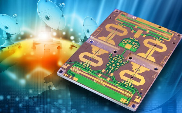
PCB radar technology also has a wide range of applications in the aerospace field, especially in aircraft radar systems. Through proper design and optimisation, PCB radar boards in aircraft can achieve the functions of weather changes, obstacle detection, etc., providing safety for aircraft. At the same time, PCB radar boards can provide accurate data support for flight navigation, altitude control and other aspects, providing assurance for aircraft performance improvement.
●High-frequency PCB boards: special circuit boards with high electromagnetic frequencies, commonly used in automotive collision avoidance systems, satellite systems, radio systems and other fields. High-frequency PCB board to achieve high-frequency signal transmission circuit board. The technology is designed to have high-speed transmission, low noise, high precision, etc. It is widely used in wireless communications, aerospace, medical equipment and other fields.
●Key materials for high-frequency microwave RF pcb circuit boards.
※Printed circuit board (PCB) circuit materials are the critical building blocks of radio frequency (RF)/microwave circuits-essentially the starting point for these circuits.PCB materials come in many different forms, and the choice of material depends heavily on the requirements of the intended application. For example, materials that reliably support high-frequency circuits in commercial wireless products can fail quickly when taken to the extremes of a military environment. A basic understanding of PCB material types and their parameters can help match the material to the application.
※As with many RF/microwave components, PCB materials are classified and compared by a number of key parameters, including relative dielectric constant (Dk or εr), dissipation factor (Df), coefficient of thermal expansion (CTE), dielectric coefficient of thermal constant (TCDk), and thermal conductivity. When classifying different PCB materials, many circuit designers start with Dk.The Dk value of a PCB material is the capacitance or energy available between a pair of very close conductors fabricated on the material compared to the same pair of conductors in a vacuum.

※Vacuum produces a reference value of 1.0, while other dielectric materials provide higher reference values. For example, commercial PCB materials typically have Dk values in the range of about 2 to 10, depending on how they are measured and how often they are tested. Conductors on materials with higher Dk values can store more energy than conductors on materials with lower Dk values.
※The Dk value of a PCB material affects the size, wavelength, and characteristic impedance of a transmission line fabricated on that material. For example, for a given characteristic impedance and wavelength, the size of a transmission line fabricated on a PCB material with a high Dk value will be much smaller than the size of a transmission line fabricated on a PCB material with a low Dk value, although other material parameters may be different. Designers faced with circuits in which loss is a key performance parameter often prefer to use PCB materials with lower Dk values because these materials have lower loss than materials with higher Dk values.
※Ceramic-filled PTFE composite RT / duroid 6035HTC with high thermal conductivity for high-power circuit applications.
※Thermal dissipation of RF/microwave circuits (especially for high power designs) is an important function characterised by the thermal conductivity of the PCB. Although standard PCB materials may have a thermal conductivity of 0.25 W / m / K, it is common to add fillers to the PCB material to increase the thermal conductivity to more favourable values (as well as better heat dissipation). For example, RO4350B, a hydrocarbon/ceramic PCB material from Rogers, has long been a reliable building block material for high-frequency applications, including automotive and cellular communications systems.
※There is a wide range of materials used for RF/microwave PCBs, from low-cost FR-4 materials to expensive PTFE-based materials. Boards composed of FR-4 materials are essentially laminates of glass-reinforced epoxy resin, whereas PTFE materials are usually reinforced by glass fibre or ceramic filler materials (although pure PTFE-based PCBs are also used). The difference in performance between these two extreme materials points to the trade-offs that PCB materials must make between cost and performance, and between the ease of processing FR-4 and the difficulty of processing PTFE materials.
Contact: Ella Ouyang
Phone: 86-13570888065
Tel: 86-0755-28632299
Email: ellaouyang@szxpcba.com
Add: Building 8, Gangbei Industrial Zone, Huangtian, Xixiang, Bao’an District, Shenzhen, China.
We chat
